University of Oregon Physics Commencement Address 2020
Here is the speech I gave at my physics commencement ceremony:
I hope that you find some meaning or utility in it.
-Matt
Here is the speech I gave at my physics commencement ceremony:
I hope that you find some meaning or utility in it.
-Matt
Behold, RoboBob.
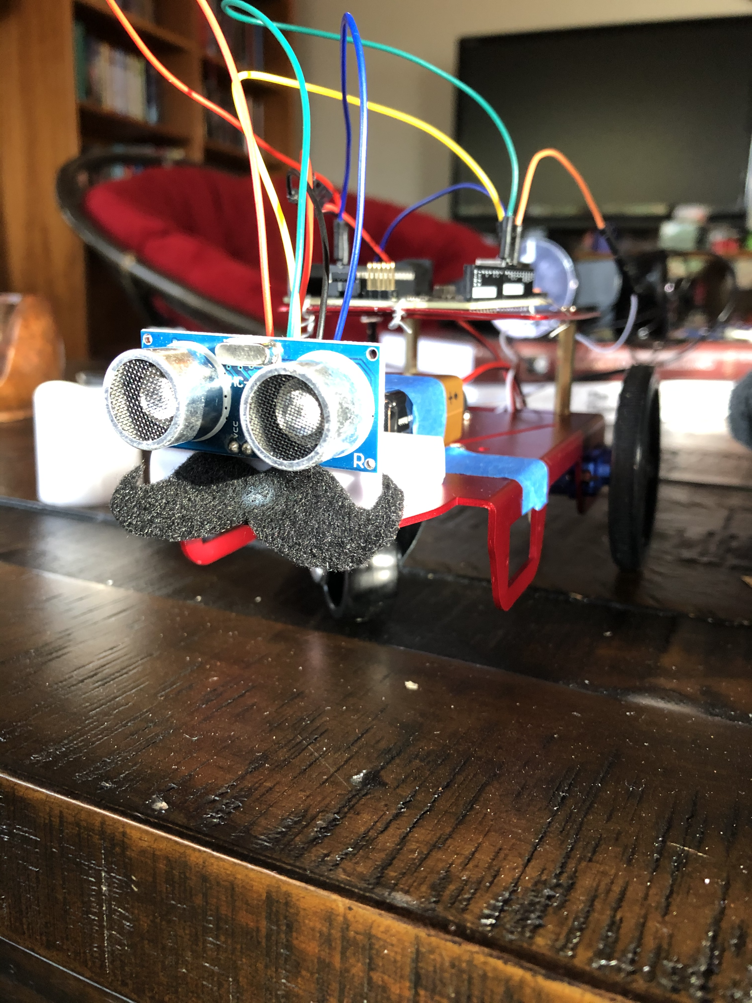
RoboBob is my first ever Arduino project! Here is what he does:
In this post, I would like to walk you through how my girlfriend and I put him together. Here is a link to the code we used.
The basic principles are as follows: RoboBob has an ultrasonic sensor mounted on the front of the rig that effectively functions as his eyes. Once the sensor detects that he is within a certain distance from the wall, it randomly picks an angle between -180º and 180º, and reorients itself in that direction. Then it moves along until it finds another wall, and the process repeats.
The reason we decided to do a random reorientation is that we wanted to write an algorithm that made the robot avoid the walls without having to hard-code the behavior. As you will see, it takes relatively few lines of code to implement. In particular, I was inspired to program RoboBob this way by bacterial chemotaxis, the process by which bacteria detect and move toward food in their environment. Essentially, a bacterium will sample the nutrient concentration at one point in space, move in some direction, and sample that concentration again. If the concentration has increased––that is, if the bacterium has moved towards the food––it will continue in that direction. Otherwise, it will randomly reorient, and begin the process over again. It turns out that this algorithm is quite efficient for ascending gradients of all types.
Obviously, there is not quite so much going on with RoboBob. This was my first project with Arduino, after all. But I wanted to try to make use of this type of random algorithm in order to accomplish some nontrivial behavior. Once I had this idea, my friend pointed out to me that I had basically made a crumbier version of a Roomba. Touché. But it is still impressive that you can actually get half-decent wall-avoidance without really telling it to do so explicitly.
So let’s get into the specifics here. I should start by giving credit to our sources. We relied heavily on work done by Eli the Computer Guy. In particular, he posted two tutorials, one on how to operate the ultrasonic sensor we used, and another on how to operate the motors. We certainly would not have been able to make our robot without his starter code and explanation.
There were three essential components to this robot: the chassis, the Arduino, and the ultrasonic sensor. We started by actually putting together the chassis and attaching the motors. I’ve had an Arduino for a while, and had not really found a compelling use for it yet. However, once we had actually constructed the skeleton, I started to get excited about making it move.
Next, we figured out how to operate the motors. The chassis kit came with a motor driver controller, which we attached on the bottom of the rig.
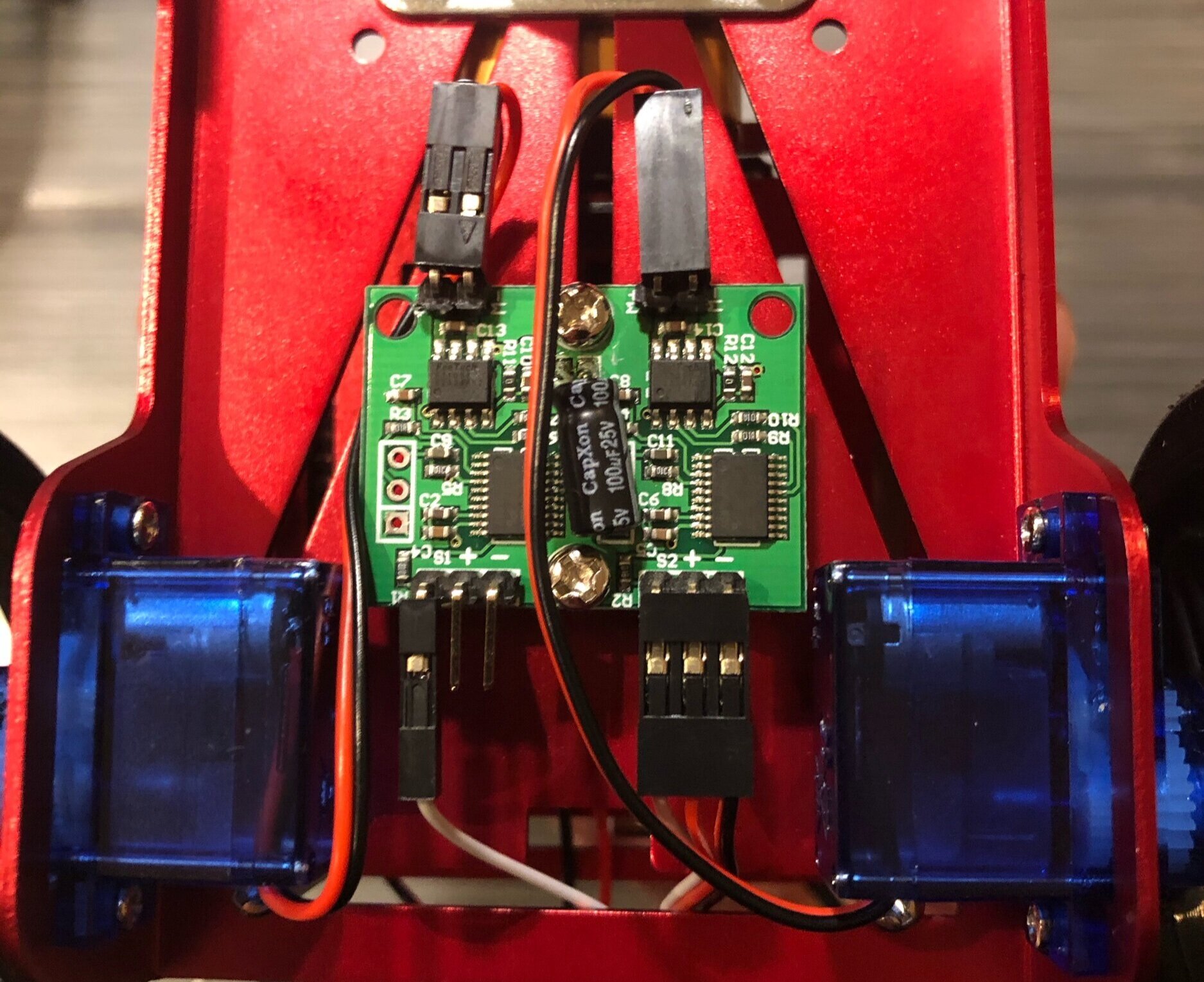
The motors (blue) and motor driver controller on the bottom of RoboBob.
The motors connect to the controller at the top. The wires coming from the bottom connect to the Arduino, for the purposes of powering (red and black wires) and controlling (two white wires) the motors. The motors can be operated simply with the Arduino by saying something like
lServo.write(60)
rServo.write(60)
which would have the robot move in a straight line. Giving the motors asymmetrical outputs causes the robot to rotate in one direction or the other.
Up close, the top of the robot looks like this:

RoboBob from above. From bottom to top: ultrasonic sensor, breadboard, 9-volt battery power source, Arduino.
It is difficult to tell from the image, but here is what is going on with the wiring. Both the motors and the ultrasonic sensor are powered by the 5V and Ground pins on the right side of the Arduino. In order to connect both systems to these pins, we first connected everything to the breadboard, and then wired that to the pins. On the right side of the Arduino, we have the digital input/output pins, which we use to control the other electronics. We wired the sensor to pins 8 and 9, and the motors to pins 10 and 11.
Now that all the components have power and a communication channel, let’s look at the code, which I have copied in full below:
/*Servo library to operate motors.*/
#include <Servo.h>

/*Pins used by the ultrasonic sensor*/
#define trigPin 8
#define echoPin 9

/*Variables to be used in the code*/
long duration;
float distanceInch;
int dir;

/*Instantiate servo objects(?)*/
Servo lServo;
Servo rServo;

void setup() {

  /*Trigger pin will output to the sensor.*/
  pinMode(trigPin, OUTPUT);
  /*Echo pin will get data from the sensor.*/
  pinMode(echoPin, INPUT);

  /*Attach servos to pins 10, 11.*/
  lServo.attach(10);
  rServo.attach(11);

  /*90 degrees corresponds to not moving. Stay still for 5 seconds.*/
  lServo.write(90);
  rServo.write(90);

  delay(5000);

}

void loop() {

  /*Next 5 lines send out ultrasonic pulse for 10 microseconds.*/
  digitalWrite(trigPin, LOW);
  delayMicroseconds(2);
  digitalWrite(trigPin, HIGH);
  delayMicroseconds(10);
  digitalWrite(trigPin, LOW);

  /*Record returning pulse.*/
  duration = pulseIn(echoPin, HIGH);

  /*2*d=vt*/
  distanceInch = duration * 0.0133 /2;

  /*Move forward*/
  lServo.write(60);
  rServo.write(60);

  /*If within 5 inches*/
  if (distanceInch < 5) {
    /*Pick a direction, either 1 or 2, at random.*/
    dir = random(1,3);

    /*Rotate in one direction by a random angle between 0 and Pi.
    875 = (period of rotation at this speed)/2 */
    if (dir == 1) {
      lServo.write(50);
      rServo.write(130);
      delay(random(875));
    }
    /*Otherwise, rotate in the other direction.*/
    else {
      lServo.write(130);
      rServo.write(50);
      delay(random(875));
    }
  }
  delay(10);
}
I tried to comment as clearly as I could, but I will summarize the logic here. After importing the servo library for the motors, you define the pins you want to use, and the variables that will be important. The variables we will need are the duration of the pulse’s travel time, the real-time distance in inches that the pulse travels, and the randomly determined direction of rotation. After setting the system up, the robot sends out a pulse and computes the distance the pulse travelled in inches. If that distance is below a certain threshold (in this case 5 inches), then it randomly selects a direction (clockwise or counterclockwise), and rotates for some random amount of time between 0 milliseconds, or half its rotational period, which we measured to be 875 milliseconds. (This is equivalent to the robot rotating between 0º and 180º, but we coded it this way because we can only control how much torque the motors exert, and how long they do it for.) Finally, the robot waits 10 milliseconds, and the process repeats.
There is certainly a lot going on here, but frankly, putting together RoboBob was easier than I expected it to be. I had a very positive first robotics experience, and I’m looking forward to the next ridiculous project, whatever it may be!